Quick reference for wiring ATmega328P ICs at 5 V and 3.3 V. 5 V uses 16 MHz crystal. 3.3 V uses 8 MHz.
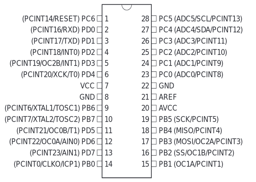
Pinout |
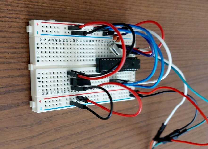
Breadboard |
5 V - 16 MHz
Standard setup. How Arduino Uno boards are wired:
    Pin 1   --> [ 10k Resistor ] --> 5V
    Pin 7   --> 5V (w/ 0.1uF Cap to GND)
    Pin 8   --> GND
    Pin 9   --> [ 16MHz Crystal ] --> [ 22pF Cap ] --> GND
    Pin 10  --> [ 16MHz Crystal ] --> [ 22pF Cap ] --> GND
    Pin 20  --> 5V (w/ 0.1uF Cap to GND)
    Pin 21  --> 5V (w/ 0.1uF Cap to GND)
    Pin 22  --> GND
Sample Makefile: Makefile
3.3 V - 8 MHz
Electrical connections are identical to 5 V circuit. Replace 5 V with 3.3 V supply, 16 MHz crystal with 8 MHz.
ATmega328P ships with its fuses(BOD level, etc.) configured for 5 V. Need to modify them. The standard Arduino bootloader requires a 16 MHz clock. Replace the default bootloader with one that works witha 8 MHz clock.
Upload the ‘ArduinoISP’ sketch from the Arduino IDE to an Arduino Uno to use it as an ISP.
    ARDUINO UNO (ISP)                       ATMEGA328P
    +-------------------+               +-------\/-------+
    |               D13 |-------------->| 19  PB5 (SCK)  |
    |               D12 |<--------------| 18  PB4 (MISO) |
    |               D11 |-------------->| 17  PB3 (MOSI) |
    |               D10 |-------------->| 1   RESET      |
    |                   |               |                |
    |                5V |-------------->| 7   VCC        |
    |               GND |-------------->| 8   GND        |
    +-------------------+               +----------------+
From the Arduino IDE, select ‘ATmega328P (3.3 V, 8 MHz)’ processor, ‘Arduino as ISP’ programmer. Upload the bootloader from the tools menu.
Sample Makefile (8 MHz): Makefile.3v3
Note: Don’t connect AREF (pin 21) to Vcc if using ADC with internal 1.1 V or AVcc reference. See datasheet section 23.5.2.